Home
Rivian R1T Solar Tonneau Cover
Status: In Progress — Phase 1 complete. Phase 2 is underway but progressing slowly — may not be complete until August 2026. Phases 3–5 are planned and may change based on actual experience.
An engineering & build log for a custom 55” × 13½” × ½” steel-framed solar panel that replaces the tonneau cover on a Rivian R1T. The panel charges a battery backup power supply stored in the truck bed, or directly powers a cooler in the bed.
Project goals
- Drop-in fit on the R1T bed channel — sized to 54⅞” to slide into existing tonneau cover channel.
- Zero-sag structure via a welded steel frame with three internal cross-beams.
- Weatherproof encapsulation of solar cells in UV-stabilized marine epoxy using the Direct Bond + Expansion Cap method.
- Field-serviceable wiring through a sealed IP67 junction box on the back skin.
- Bed-grade output to feed a portable battery bank or 12V cooler.
- Low-cost — keep costs as low as possible, and cheaper than buying a manual tonneau cover (currently $1000!!!)
Design specs
| Parameter | Value |
|---|---|
| Panel envelope | 55” × 13½” × ½” |
| Frame | Steel L-beam, 54⅞” × ½” × ½” |
| Cross-beams | 3× flat steel, 13” × ⅛”, welded at 7”, 27½”, 48” |
| Back skin | 6oz woven fiberglass, 13¼” × 55” |
| Encapsulant | UV-stabilized clear marine epoxy, slow hardener (~1.13 gal) |
| Top seal | Marine silicone expansion cap, 1/16” gap |
| Wire exits | Two drilled bus-bar pass-throughs, clay-sealed during pour |
| J-Box | Direct-solder IP67, mounted 2” from frame on back skin |
Build phases
- ✅ Phase 1 — Frame Prep & Bonding Surface — Complete. Weld, flatten, prime, test-fit in the bed.
- 🛠️ Phase 2 — Bottom-Up Layup & Hole Drilling — In progress — may not complete until August 2026; may change based on actual experience. Fiberglass back skin, amine blush removal, drill wire exits.
- 🗓️ Phase 3 — Cell Placement & Routing — Planned — may change based on actual experience. Kapton insulation, cell stringing, bus-bar routing, clay seal.
- 🗓️ Phase 4 — The Resin Pour (Direct Bond Method) — Planned — may change based on actual experience. Seal coat, flood coat, 1/16” expansion gap, torch bubbles, cure.
- 🗓️ Phase 5 — Post-Cure, Expansion Cap & J-Box Soldering — Planned — may change based on actual experience. Demold, clay removal, silicone cap, J-Box solder.
Reference
- Materials list — full bill of materials with resin volume math.
- Pro hints & watch-outs — failure modes and hard-won lessons.
- Original directions — canonical source document in
Docs/Directions.md.
Outcome so far (through Phase 1)
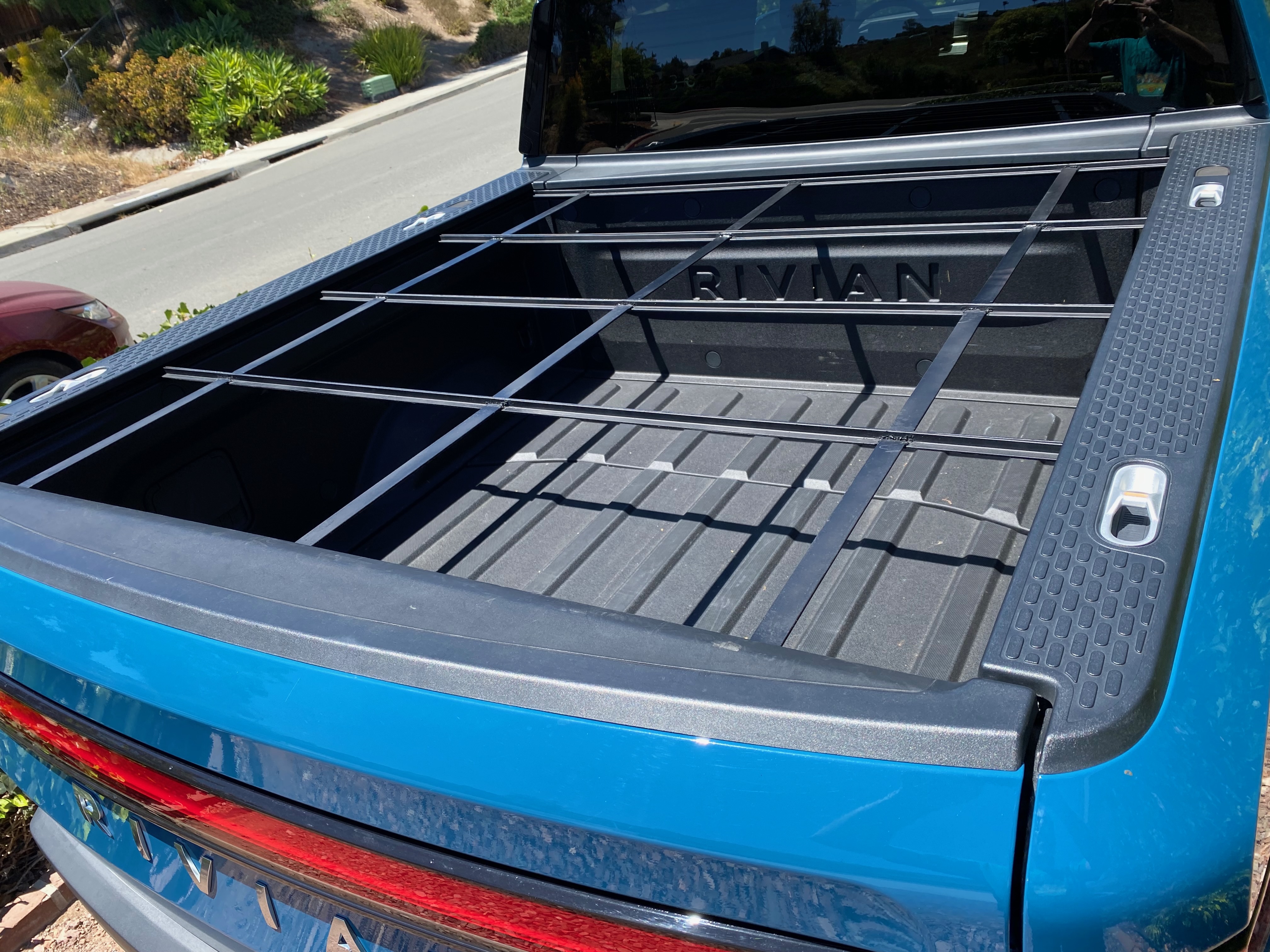
Phase 1 is complete. The steel frame is welded, flattened, primed, and test-fit in the R1T bed. Final bed fit is verified — the panel sits flush in the bed channel with a clean gap at the tailgate end, ready for the resin pour and cell stringing phases. The frame was ground down from 54 15/16” to 54 7/8” to correct a ~1/16” narrowing at the back of the channel and now drops in cleanly.
Work on Phase 2 has started but is a slower process and may not be complete until August 2026. Later phases are planned and may change based on actual experience.
Upcoming sections will cover electrical configuration, battery integration, cooler wiring, and field test results as the build progresses.